
Table of Contents
Understanding how data travels across a network is a fundamental requirement for cybersecurity and IT certifications, including CompTIA Security+, Network+, and CISSP (Domain 4: Communication and Network Security).
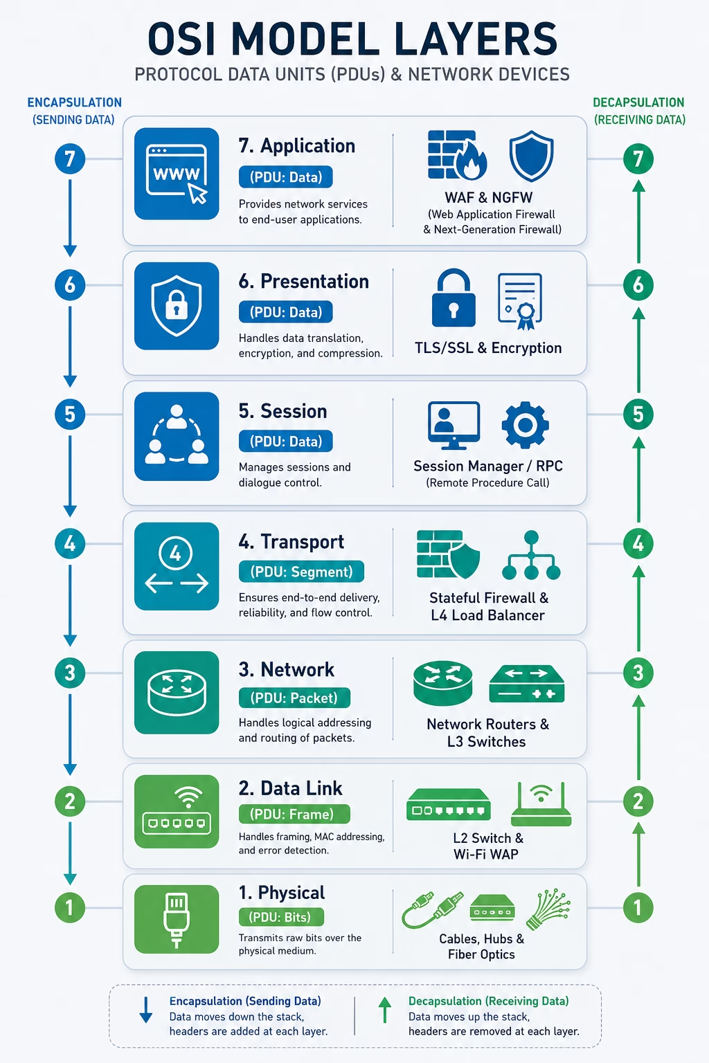
The Open Systems Interconnection (OSI) model, established by the International Organization for Standardization (ISO/IEC 7498-1), breaks down network communications into seven distinct logical layers. While modern networks run on the 4-layer TCP/IP protocol suite, the 7-layer OSI model remains the global standard for conceptualizing network traffic, troubleshooting connectivity, and implementing security controls.
This guide provides a comprehensive breakdown of all 7 layers, the Protocol Data Units (PDUs) at each stage, the physical and logical devices operating at each tier, and a real-world analogy to help you memorize the model permanently.
The Master Analogy: The International Corporate Mail System
To memorize how data moves from Layer 7 (Application) down to Layer 1 (Physical) during transmission—and back up during reception—use the International Corporate Mail Analogy:
- Layer 7 (Application): The CEO writes a message in English (“Ship 500 units to Tokyo”).
- Layer 6 (Presentation): The Executive Assistant translates the letter into Japanese and encrypts the text with a confidential cipher.
- Layer 5 (Session): The Dispatch Coordinator calls the Tokyo office, confirms they are open and ready to receive, and establishes a secure tracking session.
- Layer 4 (Transport): The Shipping Manager numbers each page (Page 1 of 5, Page 2 of 5) so none get lost, adding instructions on how to handle missing pages.
- Layer 3 (Network): The Logistics Router writes the sender and destination street addresses (IP addresses) on the outer mailing envelope.
- Layer 2 (Data Link): The Local Courier puts the envelope into a local mail truck assigned to a specific delivery route and checks the vehicle registration (MAC address).
- Layer 1 (Physical): The highway pavement, railway tracks, and delivery truck tires physically transport the physical parcel to its destination.
Memory Mnemonics for Exam Day
- Top-Down (Layer 7 to Layer 1): All People Seem To Need Data Processing (Application, Presentation, Session, Transport, Network, Data Link, Physical)
- Bottom-Up (Layer 1 to Layer 7): Please Do Not Throw Sausage Pizza Away (Physical, Data Link, Network, Transport, Session, Presentation, Application)
Detailed Breakdown of the 7 OSI Layers
Layer 7: Application Layer
The Application layer is the layer closest to the end-user. It provides network services directly to user software applications (such as web browsers, email clients, or file transfer utilities). It does not represent the application itself (like Google Chrome), but rather the communication protocols the application uses to interact with the network.
- Protocol Data Unit (PDU): Data
- Core Protocols: HTTP, HTTPS, DNS, SMTP, IMAP, SSH, FTP, Telnet, SNMP
- Associated Devices & Security Controls:
- Web Application Firewalls (WAF): Inspects HTTP/HTTPS traffic for SQL injection, Cross-Site Scripting (XSS), and application-layer attacks.
- Next-Generation Firewalls (NGFW): Performs deep packet inspection (DPI) to identify specific application traffic regardless of port.
- API Gateways: Enforces authentication and rate-limiting on REST/GraphQL endpoints.
- Common Attacks: SQL Injection, Cross-Site Scripting (XSS), HTTP Flood DDoS, DNS Poisoning.
Layer 6: Presentation Layer
The Presentation layer is responsible for formatting, translating, compressing, and encrypting data so that the Application layer of the receiving system can understand it. It ensures that data sent from one system’s application layer is readable by another system, regardless of operating system differences.
- Protocol Data Unit (PDU): Data
- Core Functions & Formats:
- Data Translation: ASCII, Unicode, EBCDIC.
- Encryption & Decryption: TLS/SSL negotiation and cryptographic formatting.
- Compression & Media Formats: JPEG, PNG, GIF, MP4, JSON, XML serialization.
- Associated Devices: TLS Termination Proxies, Hardware Security Modules (HSMs), Application Load Balancers handling SSL Offloading.
- Common Attacks: SSL/TLS downgrade attacks, cipher suite manipulation, malicious serialization attacks.
Layer 5: Session Layer
The Session layer establishes, manages, maintains, and terminates communication sessions between applications on different devices. It synchronizes dialogue control, coordinates half-duplex or full-duplex communication, and inserts checkpoints into data streams so sessions can resume if interrupted.
- Protocol Data Unit (PDU): Data
- Core Protocols: RPC (Remote Procedure Call), NetBIOS, PPTP, SCP, SOCKS5.
- Associated Devices: Session Border Controllers (SBCs in VoIP networks), Gateway Proxies.
- Common Attacks: Session Hijacking, Man-in-the-Middle (MitM) session injection, RPC buffer overflows.
Layer 4: Transport Layer
The Transport layer provides end-to-end communication services between applications on different hosts. It handles data segmentation, flow control (preventing a fast sender from overwhelming a slow receiver), error detection, and retransmission of lost packets.
- Protocol Data Unit (PDU): Segment (for TCP) / Datagram (for UDP)
- Core Protocols:
- TCP (Transmission Control Protocol): Connection-oriented, reliable protocol utilizing a three-way handshake (SYN, SYN-ACK, ACK), sequence numbers, and acknowledgments.
- UDP (User Datagram Protocol): Connectionless, lightweight protocol prioritizing speed over guaranteed delivery (ideal for DNS, VoIP, and video streaming).
- Associated Devices & Security Controls:
- Stateful Inspection Firewalls: Tracks the state of active network connections (SYN/ACK states).
- Layer 4 Load Balancers: Distributes incoming traffic across servers based on IP address and TCP/UDP port numbers.
- Addressing Mechanism: Port Numbers (e.g., Port 443 for HTTPS, Port 22 for SSH).
- Common Attacks: SYN Flood DDoS, Port Scanning, TCP Session Reset attacks.
Layer 3: Network Layer
The Network layer handles logical addressing and packet routing across multiple interconnected networks. It determines the optimal physical path for data to travel from the source network to the destination network based on network conditions, quality of service, and routing metrics.
- Protocol Data Unit (PDU): Packet
- Core Protocols: IPv4, IPv6, ICMP, IPsec, OSPF, BGP, EIGRP, RIP.
- Associated Devices & Security Controls:
- Routers: Evaluates logical destination IP addresses against internal routing tables to forward packets between different subnets and Autonomous Systems.
- Layer 3 Switches (Multilayer Switches): Combines the fast packet switching of hardware ASICs with IP routing capabilities.
- Network Firewalls (Packet Filters): Evaluates incoming packets based on source and destination IP addresses.
- Addressing Mechanism: Logical IP Addresses (e.g., 192.168.1.1 or 2001:0db8::1).
- Common Attacks: IP Spoofing, ICMP Ping of Death, Smurf attacks, BGP Route Hijacking.
Layer 2: Data Link Layer
The Data Link layer provides node-to-node data transfer across a single physical network segment (Local Area Network). It is subdivided into two distinct sublayers:
- Logical Link Control (LLC): Manages flow control, error checking, and multiplexing protocols over the physical medium.
- Media Access Control (MAC): Controls how hardware devices access the transmission medium and assigns physical hardware addresses.
- Protocol Data Unit (PDU): Frame
- Core Protocols: Ethernet (IEEE 802.3), Wi-Fi (IEEE 802.11), ARP, VLANs (802.1Q), PPP, STP (Spanning Tree Protocol).
- Associated Devices & Security Controls:
- Network Switches (Layer 2): Maintains a MAC Address Table (CAM Table) to inspect incoming frames and forward them directly to the specific destination port rather than broadcasting.
- Wireless Access Points (WAPs): Bridges wireless 802.11 frames to wired 802.3 Ethernet frames.
- Network Interface Cards (NICs): Hardware chip on a host device that encodes digital data into physical signals.
- Addressing Mechanism: Physical MAC Addresses (e.g., 00:1A:2B:3C:4D:5E).
- Common Attacks: ARP Poisoning / Spoofing, MAC Flooding (CAM Table Exhaustion), VLAN Hopping, Spanning Tree manipulation.
Layer 1: Physical Layer
The Physical layer consists of the actual hardware, physical transmission media, electrical signals, light pulses, or radio frequencies used to transmit raw, unstructured bitstreams between devices. It defines pinouts, voltages, cable specifications, and physical interface standards.
Common Attacks: Wiretapping, Physical Cable Slicing, Radio Frequency (RF) Jamming, Rogue Hardware Implants (Keyloggers, Tap Devices).
Protocol Data Unit (PDU): Bit
Core Standards & Media: Cat5e/Cat6/Cat7 Twisted-Pair Ethernet, Single-Mode and Multi-Mode Fiber Optics, Coaxial, USB, Bluetooth RF, RS-232.
Associated Devices:
Network Hubs: Dumb multiport repeaters that broadcast incoming electrical signals out to all connected ports without inspecting contents.
Repeaters & Signal Boosters: Regenerates degraded digital signals across long physical distances.
Patch Panels, Modems, and Cables.
Addressing Mechanism: None (Raw digital/analog signals: Volts, Photons, Radio Waves).
7-Layer Quick Reference Matrix
| Layer # | Layer Name | PDU | Primary Addressing | Core Hardware Devices | Example Protocols |
|---|---|---|---|---|---|
| 7 | Application | Data | Service / App Names | WAF, NGFW, API Gateway | HTTP, HTTPS, DNS, SSH, SMTP |
| 6 | Presentation | Data | Syntax / Encoding | TLS Accelerators, HSMs | TLS/SSL, JSON, XML, JPEG |
| 5 | Session | Data | Session / Connection IDs | Session Border Controllers | RPC, NetBIOS, PPTP, SOCKS5 |
| 4 | Transport | Segment / Datagram | Port Numbers | Stateful Firewalls, L4 Load Balancers | TCP, UDP |
| 3 | Network | Packet | IP Addresses | Routers, Layer 3 Switches | IPv4, IPv6, ICMP, IPsec, BGP |
| 2 | Data Link | Frame | MAC Addresses | Layer 2 Switches, WAPs, Bridges, NICs | Ethernet (802.3), Wi-Fi (802.11), ARP |
| 1 | Physical | Bit | Signal Voltage / Light | Hubs, Repeaters, Cables, Transceivers | Cat6 Copper, Fiber Optics, 1000BASE-T |
Key Takeaways
- As data moves down the stack from Layer 7 to Layer 1, each layer wraps the payload with headers in a process called Encapsulation (Data ➔ Segment ➔ Packet ➔ Frame ➔ Bits).
- When data is received, the process reverses as headers are stripped off during Decapsulation (Bits ➔ Frames ➔ Packets ➔ Segments ➔ Data).
- Memorizing devices by layer is straightforward: Hubs operate at Layer 1, Switches operate at Layer 2, Routers operate at Layer 3, Stateful Firewalls operate at Layer 4, and Web Application Firewalls operate at Layer 7.